MANAMA: A boutique hotel in Bahrain, Al Safir Hotel and Tower in Juffair, is well on its way to creating a hospitality industry record by becoming one of the first hotels to implement an internationally recognised Quality Management System (QMS).The Al Safir Hotel's QMS initiative is backed by the Labour Fund which launched a programme in June this year to enable small and medium enterprises (SMEs) in the kingdom to gain international quality management certification.
This was announced at a Press conference in the Golden Tulip Hotel yesterday.
Using the expertise of Jaffari Consultants, the Al Safir Hotel and Tower has launched an ambitious three-pronged effort to gain certification of excellence in three different areas: Quality Management System - ISO 9001:2000, Occupational Health and Safety System - OHSAS 18001 and Food Safety Management System - ISO 22000:2005.
"The Al Safir Hotel is one of the first in the kingdom to put in place the requirements for ISO 9001:2000 certification and is aiming to be amongst the first to be awarded the certification," said the Al Safir hotel general manager Abdul Hamid Halwachi.
"But I think we are even more proud that we have undertaken an extensive and multi-layered approach to the whole quality question by simultaneously seeking OHSAS 18001 and Food Safety Management System ISO 22000:2005 certification as well.
"This bold move has been made possible thanks to the support of the Labour Fund which has extended its Enterprise Development Support to include quality management and giving medium-sized organisations like ours access to expertise such as Jaffari Consultants," he added.
The consultation service will be provided by Bahrain-based Jaffari Consultants (JAFCON), which offers comprehensive consultancy services world-wide, including all type of quality management systems and productivity improvement services.
JAFCON is one of the major service providers for the QMS scheme, as well as, the other Enterprise Development Programmes of the fund.
The primary goal of the fund's quality management scheme is to raise the standard of corporate productivity and performance and enhance its competitiveness in the markets.
The quality management scheme comes under the fund's Enterprise Development Support Programme which seeks to assist and support SMEs in enhancing their productivity to enable them to develop and grow while providing high quality jobs to Bahrainis through providing access to world class consultation and training for upgrading business information systems, technology inputs and business growth and development.
"We want to show that international certificates such as the ISO, HACCP, Food Safety and OHSAS are not mere labels but actually help companies to improve performance, profitability and win international acceptability," said Labour Fund acting chief executive Abdulellah Al Qassimi.
"The BD200,000 ($530,490) pilot phase cost and initial research for this project, which the Al Safir Hotel and Tower has put to such good use, will aid in validating and recalibrating a quality management business model, and provide a road map for the full implementation phase," he added.
more
Sunday, August 31, 2008
Paper space is a sheet layout environment where you can specify the size of your sheet, add a title block, display multiple views of your model, and create dimensions and notes for your drawing.
Quick Start for Layouts There are two distinct working environments, which are represented by the Model and layout tabs.
Understand the Layout Process When you use a layout tab to prepare your drawing for plotting, you follow a series of steps in a process.
Work with Model Space and Paper Space There are several benefits to switching between model space and paper space to perform certain tasks. Use model space for creating and editing your model. Use paper space for composing your drawing sheet and defining views.
Create and Modify Layout Viewports You can create a single layout viewport that fits the entire layout or create multiple layout viewports in the layout. Once you create the viewports, you can change their size, their properties, and also scale and move them as needed.
Control Views in Layout Viewports When you create a layout, you can add layout viewports that act as windows into model space. In each layout viewport, you can control the view that is displayed.
Control Visibility in Layout Viewports You can control the visibility of objects in layout viewports using several methods. These methods are useful for emphasizing or hiding different elements of a drawing, and for reducing screen regeneration time.
Reuse Layouts and Layout Settings When you create a layout, you can choose to apply the information from an existing template.
Quick Start for Layouts
Concepts
Procedures
Commands
There are two distinct working environments, or “spaces,” in which you can create objects in a drawing.
Typically, a model composed of geometric objects is created in a three-dimensional space called model space. A final layout of specific views and annotations of this model is created in a two-dimensional space called paper space. These spaces are accessible on two or more tabs near the bottom of the drawing area: the Model tab and one or more layout tabs.
Working on the Model tab, you draw a model of your subject at 1:1 scale. Working on a layout tab, you place one or more viewports, dimensions, notes, and a title block to represent a drawing sheet.
On a layout tab, each layout viewport is like a picture frame containing a “photograph” of the model. Each layout viewport contains a view that displays the model at the scale and orientation that you specify. You can also specify which layers are visible in each layout viewport.
After you finish arranging the layout, you turn off the layer that contains the layout viewport objects. The views are still visible, and you can plot the layout without displaying the viewport boundaries.
Understand the Layout Process
Concepts
Procedures
Commands
When you use a layout tab to prepare your drawing for plotting, you follow a series of steps in a process.
You design the subject of your drawing on the Model tab (in model space) and prepare it for plotting on a layout tab (in paper space).
There is one Model tab and one or more layout tabs at the bottom of the drawing window.
Process Summary
When you prepare a layout, you typically step through the following process:
Create a model of your subject on the Model tab.
Click a layout tab.
Specify layout page settings such as plotting device, paper size, plot area, plot scale, and drawing orientation.
Insert a title block into the layout (unless you have started with a drawing template that already has a title block).
Create a new layer to be used for layout viewports.
Create layout viewports and position them on the layout.
Set the orientation, scale, and layer visibility of the view in each layout viewport.
Add dimensions and annotate in the layout as needed.
Turn off the layer containing the layout viewports.
Plot your layout.
Reuse Layouts and Layout Settings
Concepts
Procedures
Commands
When you create a layout, you can choose to apply the information from an existing template.
A layout template is a layout imported from a DWG or DWT file. When you create a layout, you can choose to apply the information from an existing template. The program has sample layout templates to use when you design a new layout environment. The paper space objects and page setup in the existing template are used in the new layout. Thus, the layout objects, including any viewport objects, are displayed in paper space. You can keep any of the existing objects from the template you import, or you can delete the objects. No model space objects are imported.
The layout templates are identified with a .dwt file extension. However, a layout template or layout from any drawing or drawing template can be imported into the current drawing.
Save a Layout Template
Any drawing can be saved as a drawing template (DWT file), including all of the objects and layout settings. You can save a layout to a new DWT file by choosing the Save As option of the LAYOUT command. The template file is saved in the drawing template file folder as defined in the Options dialog box, Support tab. The layout template has a .dwt or .dwg extension like a drawing template or drawing file, but it contains little information not essential to the layout.
When you create a new layout template, any named items, such as blocks, layers, and dimension styles, that are used in the layout are saved with the template. These definition table items are imported as part of the layout settings if you import this template into a new layout. It is recommended that you use the Save As option of the LAYOUT command to create a new layout template. When you use the Save As option, unused definition table items are not saved with the file; they are not added to the new layout into which you import the template.
If you insert a layout from a drawing or template that was not created using the Save As option of the LAYOUT command, definition table items that are used in the drawing but not in the layout are inserted with the layout. To eliminate unnecessary definition table items, use the PURGE command.
Insert a Layout Using DesignCenter
Using DesignCenter™ , you can drag a layout with its objects from any drawing into the current drawing.
When you use DesignCenter to insert a layout into a drawing, a new layout is created that includes all of the paper space objects, definition tables, and block definitions from the source layout. You can delete unneeded paper space objects. To eliminate any unnecessary definition table information from the new layout, use the PURGE command.
Comments?
draw, scale annotate in model space
Draw, Scale, and Annotate in Model Space
Concepts
Procedures
Commands
If you draw and plot from model space, you must determine and apply a scale factor to annotation objects before you plot.
You can draw and plot entirely from model space. This method is useful primarily for two-dimensional drawings that have a single view. With this method, you use the following process:
Determine the unit of measurement (drawing units) for the drawing.
Specify the display style for the drawing unit.
Calculate and set the scale for dimensions, annotations, and blocks.
Draw at full scale (1:1) in model space.
Create the annotation and insert the blocks in model space.
Plot the drawing at the predetermined scale.
Determine the Unit of Measurement
Before you begin drawing in model space, you determine the unit of measurement (drawing units) that you plan to use. You decide what each unit on the screen represents, such as an inch, a millimeter, a kilometer, or some other unit of measurement. For example, if you are drawing a motor part, you might decide that one drawing unit equals a millimeter. If you are drawing a map, you might decide that one unit equals a kilometer.
Specify the Display Style of Drawing Units
Once you have determined a drawing unit for the drawing, you need to specify the style for displaying the drawing unit, which includes the unit type and precision. For example, a value of 14.5 can be displayed as 14.500, 14-1/2, or 1’2-1/2”.
Specify the display style of drawing units with the UNITS command. The default drawing unit type is decimal.
Set the Scale for Annotations and Blocks
Before you draw, you should set the scale for dimensions, annotations, and blocks in your drawings. Scaling these elements beforehand ensures that they are at the correct size when you plot the final drawing.
You should enter the scale for the following objects:
Text. Set the text height as you create text or by setting a fixed text height in the text style (STYLE).
Dimensions. Set the dimension scale in a dimension style (DIMSTYLE) or with the DIMSCALE system variable.
Linetypes. Set the scale for noncontinuous linetypes with the CELTSCALE and LTSCALE system variables.
Hatch patterns. Set the scale for hatch patterns in the Hatch and Gradient dialog box (HATCH) or with the HPSCALE system variable.
Blocks. Specify the insertion scale for blocks either as you insert them, or set an insertion scale in the Insert dialog box (INSERT) or in DesignCenter (ADCENTER). The system variables used for inserting blocks are INSUNITS, INSUNITSDEFSOURCE, and INSUNITSDEFTARGET. This also applies to the border and title block of the drawing.
Determine the Scale Factor for Plotting
To plot your drawing from the Model tab, you calculate the exact scale factor by converting the drawing scale to a ratio of 1:n. This ratio compares plotted units to drawing units that represent the actual size of the objects you are drawing.
For example, if you plan to plot at a scale of 1/4 inch = 1 foot, you would calculate the scale factor 48 as follows:
1/4" = 12"
1 = 12 x 4
1 (plotted unit) = 48 (drawing units)
Using the same calculation, the scale factor for 1 centimeter = 1 meter is 100, and the scale factor for 1 inch = 20 feet is 240.
Sample Scale Ratios
The sample architectural scale ratios in the table can be used to calculate text sizes in model space.
Scale
Scale factor
To plot text
size at
Set drawing text
size to
1 cm = 1 m
100
3 mm
30 cm
1/8" = 1'-0"
96
1/8"
12"
3/16" = 1'-0"
64
1/8"
8"
1/4" = 1'-0"
48
1/8"
6"
3/8" = 1'-0"
32
1/8"
4"
1/2" = 1'-0"
24
1/8"
3"
3/4" = 1'-0"
16
1/8"
2"
1" = 1'-0"
12
1/8"
1.5"
1 1/2" = 1'-0"
8
1/8"
1.0"
If you are working in metric units, you might have a sheet size of 210 x 297 mm (A4 size) and a scale factor of 20. You calculate grid limits as follows:
210 x 20 = 4200 mm
297 x 20 = 5900 mm
See Also
Specify Units and Unit Formats
contd here
quick start
The process of creating and plotting a drawing file in model space is very different from the process used in manual drafting.
In AutoCAD, there are two distinct working environments that are represented by the Model and layout tabs. These tabs are located near the bottom of the drawing area.
If you are going to create a two-dimensional drawing that has one view, you can create both the model and its annotation entirely in model space, not using a layout tab. This is the traditional method for creating drawings with AutoCAD. This method is simple but has several limitations, including
It is suitable for 2D drawings only
It does not support multiple views and view-dependent layer settings
Scaling the annotation and title block requires computation
With this method, you always draw geometric objects at full scale (1:1) and text, dimensions, and other annotation at a scale that will appear at the correct size when the drawing is plotted.
See Also
Create Multiple-View Drawing Layouts (Paper Space)
Work with Sheets in a Sheet Set
contd here
draw and edit in AUTOCAD
Draw and Edit
Drawing Environment
Tool Palettes
Tool palettes can be used only in the version of the product in which they were created. For example, you cannot use a tool palette that was created in AutoCAD 2006 in AutoCAD 2005.
Customization Files with the Same Name
When loading partial menus, AutoCAD first searches the Support File Search Path (defined on the Files tab of the Options dialog box). If you try to load a customization (CUI) file that has the same name as another file, the program automatically loads the file located in the Support File Search Path, regardless of which file you specified. To avoid confusion, make sure that file names are unique.
Workspaces
When you have selected the Automatically Save Workspace Changes option in the Workspace Settings dialog box (WSSETTINGS), the current workspace is automatically saved when you close the product. However, the workspace is not saved if you close AutoCAD when no drawings are open. To ensure that the workspace is saved upon closing, either use WSSAVE to save the workspace before you close the last drawing or make sure that at least one drawing is open when you close AutoCAD.
Dynamic Input
Dynamic Input and the Command Window
Dynamic Input is not designed to replace the command window. You can hide the command window to increase your drawing area, but you will need to display it for some operations. Press F2 to hide and display command prompts and error messages as needed. You can also undock the command window and use Auto-hide to roll open or roll up the window.
Dynamic Input Guidelines
You can now enter coordinate values in a tooltip instead of on the command line. The X,Y coordinate values you enter for most commands are by default interpreted as relative polar coordinates--not absolute coordinates, as in previous releases of the product. To enter relative coordinates, you usually do not need to enter the at sign (@); you only need to enter the relative offset values. To indicate absolute coordinates, use the pound sign (#) prefix. For example, to move an object to the drawing origin, enter #0,0 at the second point prompt.
The DYNPICOORDS system variable controls whether pointer input uses relative or absolute format for coordinates. You can use symbol prefixes to temporarily override these settings:
To enter absolute coordinates when relative coordinates are displayed in the tooltip, enter #.
To enter relative coordinates when absolute coordinates are displayed, enter @.
To enter absolute world coordinate system (WCS) coordinates, enter * (an asterisk).
When dimensional input is turned on (DYNMODE = 2 or 3), the program switches to pointer input when you enter a comma (,) an angle bracket (<) or when you select multiple grip points. When you enter a dimensional value and press the TAB key, the field displays a lock icon, and the cursor is constrained by the value that you entered. You may get unexpected results if you enter values in a Dynamic Input tooltip when the cursor is off the drawing area and the tooltip is not visible. Dynamic Input is not supported for perspective views. Dimensional Input and Grips The behavior has changed when you use grips to stretch vertices when dimensional input is turned on (DYNMODE = 2 or 3). Entering a single direct distance value differs from previous releases because you are editing the segments' total length or angle value, not the vertex position. For best results, turn off dimensional input by setting DYNMODE to 0 or 1, by pressing F12, or by clicking the Dynamic Input button (DYN) on the status bar. Dimensional Input - Grip Editing and Angles When you use grips to stretch objects or when you create new objects, the dimensional input pointer displays only acute angles. That is, all angles are displayed as 180 degrees or less. Thus, an angle of 270 degrees is displayed as 90 degrees regardless of the angle direction set in the Drawing Units dialog box. Angles specifications rely on the direction of the cursor movement to determine the positive angle direction. Object Selection Cycling Use of the TAB key to cycle through objects causes different behavior, depending on the dynamic input setting: For dimensional input (DYNMODE=3): When you select multiple objects that share a common grip and then click the grip, the TAB key cycles through all the dimensions for each selected object. For pointer input (DYNMODE=1): If you enter a value during a command, use the left angle bracket (<) or comma (,) instead of the TAB key to display an additional input field. Paste Values into a Dynamic Prompt Tooltip To use PASTECLIP to paste values from the Windows Clipboard into a dynamic prompt tooltip, type a letter in the tooltip and then backspace to delete the letter before you paste the entry. Otherwise, the entry is pasted into the drawing as text. Other Drafting Issues Temporary Override Keys You can modify the keyboard response time for temporary override keys by changing settings in the Windows Control Panel. To adjust the temporary override key response time From the Windows Start menu, click Settings > Control Panel.
In the Control Panel, click Keyboard.
In the Keyboard Properties dialog box, on the Speed tab, drag the Repeat Rate slider to adjust the keyboard response time. Then click OK.
Associative Dimensions
To turn on associative dimensioning by default every time that you open a drawing, add the following line to the acad2006doc.lsp file, which is located in the Support directory:
(setvar "DIMASSOC" 2)
Use DIMREGEN to update dimensions after opening a drawing that was modified with an earlier release or after opening a drawing with external references that have been modified. If you want to update dimensions automatically, you can add the following line to the acad2006doc.lsp file in the Support directory: (command "DIMREGEN")
Solid Hatches
Drawings that contain solid hatches may produce larger plot files than drawings with other types of hatches.
Layers and Lineweight Values
To create named layer filters using lineweight filtering criteria, in the Named Layer Filters dialog box, Lineweight box, enter lineweight values as they are listed in the Lineweight List (for example, enter 0.30 mm with a space between the number and "mm"). You can also use wild-card characters (for example, enter *3*) to filter using lineweight criteria. If you want to filter for multiple lineweights, the values must be separated by commas without spaces (for example, enter 0.30 mm,0.1*). Custom lineweight values are implemented by using plot styles and are not applicable to layers, objects, or named layer filters.
Nonrectangular Viewports
Assigning a noncontinuous linetype to a nonrectangular viewport can result in model space geometry that is irregularly clipped inside the viewport, or it can cause AutoCAD to become unstable.
When you use the JPGOUT, PNGOUT, BMPOUT, and TIFOUT commands in a layout that contains nonrectangular viewports with a 3D setting of SHADEMODE and with all objects and viewports selected, portions of other viewports may be obscured and objects may not be visible. You can use the PUBLISH command to create more accurate raster output.
Do not freeze layers that contain nonrectangular viewports; instead, turn off layers with nonrectangular viewports or set the Plot property of the layer to No Plot. When you freeze a layer that contains a nonrectangular viewport, the viewport boundary becomes rectangular. Objects in the viewport that should be clipped by the boundary of the nonrectangular viewport appear to be clipped, but when you regenerate or plot the drawing, the objects are not clipped as you expect. To correct the problem once it exists, you must thaw the layer and then regenerate the drawing.
AutoSnap Markers
When you use object snaps, AutoSnapTM markers identify snap locations as you move your pointing device over them. Although these markers normally disappear when you move your pointing device to a different part of the drawing, they may remain on the screen under specific conditions. Only the Intersection and Apparent Intersection object snaps work this way, and only when the Display Polar Tracking Vector option is cleared on the Drafting tab in the Options dialog box. The AutoSnap markers in this situation affect the display of the drawing only; they are not part of the drawing itself. To remove the markers, close and reopen the drawing.
Nested Xrefs
You can resolve nested external references (xrefs) with relative paths. The relative path is based on the location of the original host drawing of the xref, not the currently open drawing. When a nested xref is reported as "not found," edit the path in its original host drawing, not in the drawing that is currently open. The setting for the VISRETAIN system variable no longer determines how relative paths of nested xrefs are resolved.
Project Organization
Sheet Sets
The Sheet Set Manager is not fully functional if
A command is active.
No drawing is open.
The sheet set is locked by another user.
A lock icon displayed in front of the sheet set name in the Sheet Set Manager indicates that the sheet set is locked. Hold your cursor over the lock icon to view a tooltip that shows who has the sheet set locked.
When you select a sheet in the Sheet Set Manager, the sheet's status may be listed incorrectly as Locked for Edit by Unknown in the Details area. To update the sheet's status, open the sheet.
On Novell networks, the Sheet Set Manager does not display a lock icon when the sheet set is locked by another user. Shortcut menu options in the Sheet Set Manager are displayed as if they are available for use, but some of them may not work.
If you remove a sheet from a sheet set and then import the sheet back into the sheet set, fields that display sheet set information in block attributes are displayed as pound signs. To correct these fields, you can either re-create the field or reinsert the block. If you re-create the field, because the sheet is already in a sheet set, you should use a sheet set property field, not a placeholder field.
Sheet set fields (fields that were selected from the sheet set category) behave differently than other types of fields. By default, other types of fields update automatically when you save the drawing or when you use REGEN. In contrast, sheet set fields store the last values that were used, and they display these stored values if the information referenced by the sheet set field is not accessible. To update the value in a sheet set field, use the UPDATEFIELD command. If the information referenced by the sheet set field is still not accessible, the value for the field will be displayed as ####.
Using One DWT for Page Setups and Blocks on a Network
Some sheet set functions are unavailable when two network users access a sheet set that uses the same drawing template file (DWT) for label and callout blocks, sheet template, and page setup overrides. To avoid this problem, do not use the same DWT file for storing page setups and block libraries.
more
importing text files into AUTOCAD
To import text files
Click Draw menu Text Multiline Text.
Specify opposite corners of a bounding box to define the width of the multiline text object.
Right-click in the editor. Click Import Text.
The size limit for an imported file is 32 KB.
In the Select File dialog box, double-click the file you want to import, or select the file. Click Open.
The text is inserted at the cursor location.
Change the text as needed.
To save your changes and exit the editor, use one of the following methods:
Click OK on the toolbar.
Click in the drawing outside the editor.
Press CTRL+ENTER.
Draw toolbar
Command line: MTEXT
To update a field manually
Double-click text.
Select the field to update and right-click. Click Update Field
To edit single-line text
Click Modify menu Object Text Edit.
Select a single-line text object.
In the in-place editor, enter the new text.
Press ENTER.
Select another text object to edit, or press ENTER to end the command.
Command line: DDEDIT
To find specified text in a drawing
Click Edit menu Find.
In Find Text String, enter the text you want to find.
In Search In, select Entire Drawing or click the Select Objects button to select one or more text objects.
Click Options to specify the types of text to include in the search, whether to find whole words only, and whether to match the case of the specified text.
Click Find.
The Context area displays the found text with its surrounding context.
To zoom to the found text in the drawing, click Zoom To.
Click Close.
Command line: FIND
To replace text
Click Edit menu Find.
In Find Text String, enter the text you want to find.
In Search In, select Entire Drawing or click the Select Objects button to select one or more text objects.
Click Options to specify the types of text to include in the search, whether to find whole words only, and whether to match the case of the specified text.
In Replace With, enter the text with which you want to replace the found text.
Click Find.
The Context area displays the found text with its surrounding context.
Use one of the following methods:
To replace only the found instance of the text string, click Replace.
To replace all instances of the text in Find Text String, click Replace All.
The replacement is confirmed in the status area at the bottom of the dialog box.
Click Close.
Command line: FIND
To create single-line text
Click Draw menu Text Single Line Text.
Specify the insertion point for the first character. If you press ENTER, the program locates the new text immediately below the last text object you created, if any.
Specify the height of the text. This prompt is displayed only if text height is set to 0 in the current text style.
A rubber-band line is attached from the text insertion point to the cursor. Click to set the height of the text to the length of the rubber-band line.
Specify a text rotation angle.
You can enter an angle value or use your pointing device.
Enter the text. At the end of each line, press ENTER. Enter more text as needed.
If you specify another point during this command, the cursor moves to that point, and you can continue typing. Every time you press ENTER or specify a point, a new text object is created.
Press ENTER on a blank line to end the command.
Command line: TEXT
To insert symbols or special characters in multiline text
Double-click a multiline text object to open the In-Place Text Editor.
On the expanded toolbar, click Symbol.
Click one of the options on the menu, or click Other to display the Character Map dialog box.
To access the Character Map dialog box, you must have charmap.exe installed. See Microsoft® Windows® Help for information about adding programs to your system.
In the Character Map dialog box, select a font.
Select a character, and use one of the following methods:
To insert a single character, drag the selected character into the editor.
To insert multiple characters, click Select to add each character to the Characters to Copy box. When you have all the characters you want, click Copy. Right-click in the editor. Click Paste.
To save your changes and exit the editor, use one of the following methods:
Click OK on the toolbar.
Click in the drawing outside the editor.
Press CTRL+ENTER.
Draw toolbar
Command line: MTEXT
TEXT IN CELLS, EDITING
To edit text in a table cell
Double-click inside the cell whose text you want to edit, or select the cell and click Edit Cell on the shortcut menu.
Use the Text Formatting toolbar or the shortcut menu to make changes.
To save the changes and exit, click OK on the toolbar, press CTRL+ENTER, or click outside the cell.
To remove selection from the table, press ESC.
To enter text in a table
Click inside a table cell, and start to enter text.
The Text Formatting toolbar is displayed.
Use the arrow keys to move the cursor in text inside a cell.
To create a line break within a cell, press ALT+ENTER .
To override the text style specified in the table style, click the arrow next to the Text Style control on the toolbar and select a new text style.
The text style you select is applied to the text in the cell and any new text that you enter in the cell.
To override the formatting in the current text style, first select text as follows:
To select one or more characters, click and drag the pointing device over the characters.
To select a word, double-click the word.
To select all the text in the cell, triple-click in the cell. (You can also right-click. Click Select All.)
On the toolbar, make format changes as follows:
To change the font of the selected text, select a font from the list.
To change the height of the selected text, enter a new value in the Height box.
To format text in a TrueType font with boldface or italics, or to create underlined text for any font, click the corresponding button on the toolbar. SHX fonts do not support boldface or italics.
To apply color to selected text, choose a color from the Color list. Click Other to display the Select Color Dialog BoxSelect Color dialog box (see page 37).
Use the keyboard to move from cell to cell:
Press TAB to move to the next cell. In the last cell of the table, press TAB to add a new row.
Press SHIFT+TAB to move to the previous cell.
When the cursor is at the beginning or end of text in a cell, use the arrow keys to move the cursor to adjacent cells. You can also use CTRL+an arrow key.
When text is highlighted in a cell, press an arrow key to remove selection and move the cursor to the beginning or end of the text in the cell.
Press ENTER to move down one cell.
To save your changes and exit, click OK on the toolbar or press CTRL+ENTER .
more
Saturday, August 30, 2008
Transponder for RFID
An RFID transponder is a special kind of radio transmitter and reciever. It is activated when it receives a signal of a specific kind. RFID transponders are present in smart cards and Radio Frequency Identification tags.
(go to RFID articles)
Index of related articles:
Active Tag (Active RFID Tag)Amplitude Modulation (AM)Antenna (RFID Tag Antenna)Anti-collisionBack scatter (RFID back scatter)Bi-directionalContactless smart cardChipless RFID tagContactless Credit CardsClosed Systems (or Closed Loop Systems)Code plate (RFID code plate)Continuous Wave (CM)Electromagnetic Interference (EMI)Electronic Article Surveillance (EAS)Electronic Product Code (EPC)Error Correcting Code (ECC)Error Correcting ModeError Correcting ProtocolExciteFactory ProgrammingField ProgrammingFrequency Modulation (FM)Frequency Shift Keyed Modulation (FSKM)Frequency HoppingHarvestInductive CouplingModulationPassive RFID Tag (or Passive Tag)Phase Modulation (PM)Pulse DurationRF FibersRFID ReaderRFID Tag CollisionRFID tagSmart label (RFID Smart Label)RFID Reader CollisionSmart cardsTransponder for RFID
more
RFID tag


Using RFID to improve your business
What is RFID? Imagine that you're the supervisor of a hospital. Before giving medication to a patient or even perform surgergy on him, you'd better make sure this is the right patient! With RFID, as long as a patient wears a special wrist band, when doctors and nurses meet him, they can magically find out who exactly this patient is. In fact, they could even locate the position of any patient in the hospital in a snap.
How does it work?
The wrist band contains a chip called an RFID tag which stores an unique id for the patient. The tag can be as small as a grain of a rice or can be as large as a book. Doctors can use a hand-held device called an RFID reader to read the unique id in RFID tag. The best part is that, they don't need to put the reader in front of the tag. As long as they're within say a few meters, the reader can find it. It works even if RFID tag is hidden such as inside a pocket. To detect where a particular patient is, we can just install RFID readers in door frames.
This is just one application of RFID.
Airlines around the world are sticking RFID tags to baggages that store either a unique id for the baggages or some information of the passengers, so that the passenges know exactly where their baggages are. WalMart, the largest retailer in the world, is using RFID tags for tracking the products on its supply chain. Many car keys already contain an RFID tag and the cars will check if the RFID tag is indeed there before they can be ignited. Many organizations are using RFID tags in security bages for access control. In Hong Kong, a very popular application of RFID is the Octopus card. It is used as e-cash and can be used as an access control card. Each such Octopus card contains an RFID tag that stores the amount of cash remaining.
What is the cost of an RFID system?
Tags may cost from MOP3 to MOP80 each or much more, depending on what features you'd like. For example, some tags can be written to just once in factory (like those used to track patients) but some can be written many times during use (like the Octopus cards); some tags can be read only within a inch from the reader but some can do in 10 meters or even more; some tags can store only a number of say 12 digits but some can store several pages of information or more. RFID readers may cost from MOP4,000 or much more, again depending on the features (read range, speed, accuracy and etc). As more and more companies are using RFID, the costs are dropping continuously, so you should keep an eye on this technology even if at the moment the cost is still too high for you.
So, would you be interested in using RFID?
If you have any questions, please contact us at 781313 or kent at cpttm dot org dot mo
An RFID tag is a microchip combined with an antenna in a compact package; the packaging is structured to allow the RFID tag to be attached to an object to be tracked. "RFID" stands for Radio Frequency Identification.
The tag's antenna picks up signals from an RFID reader or scanner and then returns the signal, usually with some additional data (like a unique serial number or other customized information).
RFID tags can be very small - the size of a large rice grain. Others may be the size of a small paperback book.
See also active RFID tag and passive RFID tag
(go to RFID articles)
Index of related articles:
Active Tag (Active RFID Tag)Amplitude Modulation (AM)Antenna (RFID Tag Antenna)Anti-collisionBack scatter (RFID back scatter)Bi-directionalContactless smart cardChipless RFID tagContactless Credit CardsClosed Systems (or Closed Loop Systems)Code plate (RFID code plate)Continuous Wave (CM)Electromagnetic Interference (EMI)Electronic Article Surveillance (EAS)Electronic Product Code (EPC)Error Correcting Code (ECC)Error Correcting ModeError Correcting ProtocolExciteFactory ProgrammingField ProgrammingFrequency Modulation (FM)Frequency Shift Keyed Modulation (FSKM)Frequency HoppingHarvestInductive CouplingModulationPassive RFID Tag (or Passive Tag)Phase Modulation (PM)Pulse DurationRF FibersRFID ReaderRFID Tag Collision
RFID tag
Smart label (RFID Smart Label)RFID Reader CollisionSmart cardsTransponder for RFID
more
Product Certifications
• GOST - R
• CE Mark
The CE mark is a mandatory European marking for certain product groups to indicate conformity with the essential health and safety requirements set out in European Directives. The letters 'CE' are an abbreviation of Conformité Européenne, French word for European conformity. The CE mark must be affixed to a product if it falls under the scope of 'New Approach' Directives of European union.Without the CE marking, and thus without complying with the provisions of the Directives, the product may not be placed in the market or put into service in the fifteen member states of the European Union and Norway, Iceland and Liechtenstein. However, if the product meets the provisions of the applicable European Directives, and the CE mark is affixed to a product, these countries may not prohibit, restrict or impede the placing in the market or putting into service of the product.The CE Mark is compulsory within the context of the application of EC New Approach Directives. Thus, CE marking can, be regarded as the product’s ‘trade passport’ for Europe. Notified bodies are recognized organizations within Member States, which can certify conformity assessment on the basis of the New Approach Directives.
URS Inspection Ltd. is collaborated with notified body of Europe for such certification.
KEY DIRECTIVES
Machinery Safety - 98/37/EECAll Machines in the European Economic Area (EEA) from January 1st 1995 must comply with the Machinery Directive and be safe. Also all components which are supplied separately to fulfill a safety function when in use and the failure or malfunctioning of which endangers the safety or health of exposed persons.
EMC - 2004/108/EC The EMC Directive applies to apparatus liable to cause electromagnetic disturbance or the performance of which is liable to be affected by such disturbance.
Low Voltage Equipment – 2006/95/ECThe Low Voltage Directive applies to all electrical equipment designed for use with a voltage rating between 50 and 1,000v for alternating current and between 75V and 1,500V for direct current. These voltage criteria define the scope of the directive rather than the limit at which you start applying the regulations (e.g. hazards in 12Vdc circuits of a 240Vac supplied computer are covered under the LVD).
Pressure Equipment – 97/23/ECThis directive covers equipments which affects equipment operating at a pressure greater than 0.5 bars, entered into force and is mandatory from May 2002.
Medical Devices General - 93/42/EECAll medical products marketed in European Union must carry the CE Marking under Medical Device directive. There are essential requirements in the MDD (such as safety, efficacy and EMC), and products must meet all applicable requirements.
Construction Products Directive – 89/106/EEC
Construction Product means any products, which is produced for incorporation in a permanent manner in construction works, including both building and civil engineering works.
Personal Protective Equipment Directive – 89/686/EECAll devices or appliances and integrated units of several devices or appliances designed to be worn or held by an individual for protection against one or more health and safety hazards or the execution of specific activity.
Toys Safety– 88/378/EECThis Directive shall apply to toys. A 'toy' shall mean any product or material designed or clearly intended for use in play by children of less than 14 years of age.
Simple Pressure Vessel - 87/404/EEC'Simple pressure vessel' means any welded vessel subjected to an internal gauge pressure greater than 0,5 bar which is intended to contain air or nitrogen and which is not intended to be fired with maximum working pressure of the vessel shall not exceed 30 bar and the product of that pressure and the capacity of the vessel (PS·V) shall not exceed 10 000 bar / litre and minimum working temperature must be not lower than minus 50 °C and the maximum working temperature shall not be higher than 300 °C for steel and 100 °C for aluminum or aluminum alloy vessels.
OTHER DIRECTIVES
Gas Appliances Directive – 90/396/EEC
Lifts Directive – 95/16/EC
Drag Lifts Directive – 2000/9/EC
Efficiency of Hot Water Boiler Directive – 92/42/EEC.
Transportable Pressure Equipments Directive – 99/36/EC
Radio & telecommunication Terminal Equipment- 99/5/EC
Packaging & Packaging Waste. – 94/62/EC
Apply for Certification at ce@ursindia.com
URS offers various services worldwide and these services with accreditations where applicable, whilst following uniform management system, are operated by separate legal entities within the group. For status of individual scheme and accreditation, contact URS office or email at info@ursindia.com
more
Friday, August 29, 2008
Plant Export
Phytosanitary Certificate Issuance and Tracking System
The Phytosanitary Certificate Issuance and Tracking (PCIT) system tracks the inspection of agricultural commodities and certifies compliance with plant health standards of importing countries. This capability provides USDA/APHIS/PPQ better security, reporting functions, and monitoring capabilities for exported commodities.
Phytosanitary Certificate Issuance and Tracking SystemAccess to the PCIT system is available nationwide. However, not all locations are currently using the system. Please check with local phytosanitary authorities before submitting applications through the PCIT system. For further information on the PCIT system, click on the "Contact Us" link located at the bottom right of each PCIT screen.
Webinar TrainingWeb based (webinar) training has been used to present an introduction to the PCIT system to both government (Authorized Certification Officials (ACOs) and industry personnel. The sessions last approximately two hours and walk people through the PCIT system.
PCIT ACO Webinar, Version 3.1 (WMV; 10.87 Mb)
PCIT Industry Webinar, Version 3.1 (WMV; 11.46 Mb)
Last Modified: March 7, 2008
more
PHYTO home
PHYTO is AQIS's plant and plant product export conditions database.
PHYTO contains information about the conditions to export plants and plant products, including fruit, vegetables, seeds, grains, cut flowers and timber from Australia. It is a simple and convenient reference tool detailing the requirement for Import Permits, Phytosanitary Certificates, Additional Declarations and/or treatments, and also any other relevant export information and documentation.
Please be aware that the information in PHYTO is intended as a guide only and should not be taken as definitive or exhaustive. While all reasonable efforts are made to ensure this information provided is accurate, it may be subject to change without notice. Exporters should make their own inquiries in relation to the importing country's requirements, and are encouraged to ensure compliance with the requirements of the Plant Protection Authority of the importing country, and also with other regulatory and advisory bodies prior to and after export.
Navigating PHYTO is easy. The database has been divided into seven sections: PHYTO home, Search, What's changed, Alerts, Contacts, Help and Documents. Simply select the most appropriate section and follow the instructions.
For further information regarding plant and plant product export conditions, please contact your nearest AQIS office.
Top
more
Sanitary and Phytosanitary requirements
SANITARY AND PHYTOSANITARY MEASURES:
INTRODUCTION
Understanding the WTO Agreement on Sanitary and Phytosanitary Measures
Contents
Abbreviations Introduction Questions and answers
May 1998
The Agreement on the Application of Sanitary and Phytosanitary Measures (the "SPS Agreement") entered into force with the establishment of the World Trade Organization on 1 January 1995. It concerns the application of food safety and animal and plant health regulations.
This introduction discusses the text of the SPS Agreement as it appears in the Final Act of the Uruguay Round of Multilateral Trade Negotiations, signed in Marrakesh on 15 April 1994. This agreement and others contained in the Final Act, along with the General Agreement on Tariffs and Trade as amended (GATT 1994), are part of the treaty which established the World Trade Organization (WTO). The WTO superseded the GATT as the umbrella organization for international trade.
The WTO Secretariat has prepared this text to assist public understanding of the SPS Agreement. It is not intended to provide legal interpretation of the agreement.
INTRODUCTION Back to topThe Sanitary and Phytosanitary Measures Agreement
Problem: How do you ensure that your country’s consumers are being supplied with food that is safe to eat — "safe" by the standards you consider appropriate? And at the same time, how can you ensure that strict health and safety regulations are not being used as an excuse for protecting domestic producers?
The Agreement on the Application of Sanitary and Phytosanitary Measures sets out the basic rules for food safety and animal and plant health standards.
It allows countries to set their own standards. But it also says regulations must be based on science. They should be applied only to the extent necessary to protect human, animal or plant life or health. And they should not arbitrarily or unjustifiably discriminate between countries where identical or similar conditions prevail.
Member countries are encouraged to use international standards, guidelines and recommendations where they exist. However, members may use measures which result in higher standards if there is scientific justification. They can also set higher standards based on appropriate assessment of risks so long as the approach is consistent, not arbitrary.
The agreement still allows countries to use different standards and different methods of inspecting products.
Key Features
All countries maintain measures to ensure that food is safe for consumers, and to prevent the spread of pests or diseases among animals and plants. These sanitary and phytosanitary measures can take many forms, such as requiring products to come from a disease-free area, inspection of products, specific treatment or processing of products, setting of allowable maximum levels of pesticide residues or permitted use of only certain additives in food. Sanitary (human and animal health) and phytosanitary (plant health) measures apply to domestically produced food or local animal and plant diseases, as well as to products coming from other countries.
Protection or protectionism?
Sanitary and phytosanitary measures, by their very nature, may result in restrictions on trade. All governments accept the fact that some trade restrictions may be necessary to ensure food safety and animal and plant health protection. However, governments are sometimes pressured to go beyond what is needed for health protection and to use sanitary and phytosanitary restrictions to shield domestic producers from economic competition. Such pressure is likely to increase as other trade barriers are reduced as a result of the Uruguay Round agreements. A sanitary or phytosanitary restriction which is not actually required for health reasons can be a very effective protectionist device, and because of its technical complexity, a particularly deceptive and difficult barrier to challenge.
The Agreement on Sanitary and Phytosanitary Measures (SPS) builds on previous GATT rules to restrict the use of unjustified sanitary and phytosanitary measures for the purpose of trade protection. The basic aim of the SPS Agreement is to maintain the sovereign right of any government to provide the level of health protection it deems appropriate, but to ensure that these sovereign rights are not misused for protectionist purposes and do not result in unnecessary barriers to international trade.
Justification of measures
The SPS Agreement, while permitting governments to maintain appropriate sanitary and phytosanitary protection, reduces possible arbitrariness of decisions and encourages consistent decision-making. It requires that sanitary and phytosanitary measures be applied for no other purpose than that of ensuring food safety and animal and plant health. In particular, the agreement clarifies which factors should be taken into account in the assessment of the risk involved. Measures to ensure food safety and to protect the health of animals and plants should be based as far as possible on the analysis and assessment of objective and accurate scientific data.
International standards
more
glossary
Table of Contents
I. INTRODUCTION
II. INTERNATIONAL ORGANIZATIONS AND AGREEMENTS
A. World Trade Organization
1. Researching the WTO and the Agreement on Agriculture
B. United Nations Entities 1. Researching UN Entities
C. Other International Organizations
III. REGIONAL TRADE ORGANIZATIONS AND AGREEMENTS
A. The Americas
1. North American Free Trade Agreement (NAFTA)
2. Other Regional Trade Agreements and Associations
B. Europe
1. European Union
a. Researching EU Agricultural Law2. Other European Regional Trade Agreements and Associations C. Asia D. Africa
IV. UNITED STATES TRADE IN AGRICULTURAL PRODUCTS
A. International Trade Agreements
B. Domestic Legislation
C. Administrative Agencies
D. Administrative and Judicial Decisions
V. TRADE LAWS OF OTHER COUNTRIES
A. Sources of Foreign Agricultural Trade Laws
B. Tariff Databases
C. General Resources for Finding Foreign Laws
VI. BIBLIOGRAPHIES OF BOOKS AND ARTICLES
VII. RESEARCH GUIDES AND LINKS
VIII. STATISTICS
more
Wednesday, August 27, 2008
The CE Marking Process
Step 1: Identify the directive(s) that are applicable to your product. You can download these directives at free of cost from the web site of European Union.
Step 2: Identify the conformity assessment procedure that must be taken. This could be self-declaration, involve testing, inspection or quality system assessment from a notified body or a combination of these. The conformity assessment procedure will differ depending on your product and the directive in respect of which you will get CE marking.
Step 3: Determine the dates by which you must take action. This will be the date that the directive comes into force. The majority of directives are already in force. In these cases, it is an offence to place a product on the market without CE marking because it indicates a presumption of conformity with all relevant legislation.
Step 4: Identify if there are any Harmonised European Standards applicable to your product. These are not always mandatory for manufacturers, although there is a presumption that conformity to these standards will give conformity with the relevant part of the directive. Manufacturers should follow harmonised standards, whenever possible or appropriate.
Step 5: Ensure the product complies with all the essential requirements of the directive(s). Take appropriate measures to comply or identify existing data and test reports.
Step 6: Identify whether independent assessment of your conformity to the directive or some aspects of it, is required from a notified body. This will be stated in the directive and is dependent upon the product you are getting CE marking for. You must not affix CE marking to your product until all necessary certifications have been obtained from the notified body.
Step 7: Maintain technical documentation required by the directives. Your technical documentation should support your compliance with the requirements of the directive. It is essential to retain this documentation.
Step 8: Prepare the declaration of conformity and the required supporting evidence. The declaration of conformity along with the technical documentation should be made available to competent authorities (EU Members) upon request.
Step 9: Check that no other purely national requirements exist in the countries, where the product will be sold. These may include national standards, labelling or packaging requirements.
Step 10: Affix CE marking on your product and/or its packaging and accompanying literature as stated in the directive View more technical specifications ...-->
more
Tuesday, August 26, 2008
One sixth of the world's people live in India and one third of the world's poor
. USAID's program in India supports U.S. national interests and contributes significantly to Indian development. Although constrained since 1998 by the imposition of sanctions imposed under the "Glenn Amendment", the program addresses four key U.S. national interests: (1) economic prosperity achieved through opening markets; (2) global issues of population growth, infectious diseases, and climate change; (3) development and democracy concerns of alleviating poverty, reducing malnutrition, and improving the status of women; and (4) humanitarian response by saving lives and reducing suffering associated with disasters.
In 2001, USAID addressed the suffering and dislocation caused by a major earthquake which rocked the state of Gujarat on January 26. In the first weeks after the quake, the United States Government marshalled $12.8 million in emergency assistance. USAID has reprogrammed another $10 million in previously budgeted funds for the Gujarat reconstruction effort. USAID is working with the Government of India (GOI) and nongovernmental organizations (NGOs) to strengthen their ability to anticipate and respond to future disasters.
Prospects for India's future are bright but approximately 360 million still live in absolute poverty. Many challenges need to be addressed to reduce the pervasive poverty. India is surpassed only by China in population. The high rate of population growth, particularly in urban areas, hits hardest at the poor. Despite gains in food production, nearly half of India's children are malnourished. Although the percentage of HIV infections per capita is small, India is second only to South Africa in the number of HIV infections. India contributes to the world's caseload of other infectious diseases, such as tuberculosis and polio. Further, it is the sixth-largest and second-fastest growing producer of greenhouse gases. Large central and local-state government fiscal deficits, reflected in deteriorating infrastructure, threaten the sustainability of impressive gains in poverty reduction over the past several decades.
USAID's non-humanitarian assistance programs were interrupted in May 1998 by the imposition of sanctions on U.S. assistance. In March 2000, a presidential waiver was issued that allowed USAID to resume financial sector reform activities.
Other USAID, centrally funded programs in India complement the bilateral population stabilization, child survival, HIV/AIDS and micro-enterprise activities. The American Schools and Hospital Abroad program helps strengthen Indian hospitals that demonstrate American ideas and practices.
Development Challenge
India's ability to achieve sustainable growth and reduce poverty depends greatly on its ability to stabilize population growth. The Indian population has already reached one billion; it will surpass China's population by 2040. Since a lack of access to quality reproductive health services hinders population stabilization, the USAID program focuses on improving the quality and access to reproductive health services in India's most populous state, Uttar Pradesh (170 million people
more
Need to source equipment and accessories for the Hospitality industry ? We help you make the right choice !One Stop Shop is associated with major manufacturers of Essentials for the Hotel, Restaurant and Food industries. We can monitor availability of products and give you the economics of procurement and delivery at your doorstep.
more
more
Cost and Price
Restaurant Costing
Food Costs 30
Salaries 15
O/H 40
Profit 15
Price 100
Manufacturing Unit
RM 60
Salaries 10
O/H 10
Profit 20
Price 100
Software Unit
RM 0
Salaries 60
O/H 20
Profit 20
Price 100
Food Costs 30
Salaries 15
O/H 40
Profit 15
Price 100
Manufacturing Unit
RM 60
Salaries 10
O/H 10
Profit 20
Price 100
Software Unit
RM 0
Salaries 60
O/H 20
Profit 20
Price 100
Monday, August 25, 2008
ISO 9001 Changes 2008
ISO 9001, like all standards is subject to periodic review to determine whether it is still relevant, whether it needs to be updated or whether it should be discarded. The review period is around 5 – 6 years so, since the current version was issued in the year 2000, the standard is due for revision and re-issue.
The revision process for ISO 9001 is designed such that whenever there are significant changes to be made (major revision), the next revision will be less significant (minor). Since the revisions issued in 2000 were major, it follows that the next one will be minor. Indeed, the proposed changes are more based on the clarification of points already in the standard rather than the inclusion of new requirements.
However, the proposed changes to ISO 9001’s ‘sister’ standard, ISO 9004, are much more significant though this is only a ‘guidance’ document rather than a requirements standard. ISO 9001:2000 is due for an update this year. It is currently at Draft International Standard (DIS) stage and is likely to be published in the autumn of 2008.
What does this mean for you, if you are already registered to ISO 9001:2000?
In reality there will be little impact, it seems that the changes to the standard are very small. It will replace ISO 9001:2000 but each organisation will be given approximately one year after its publication to make any updates. There should not be any major disruption to your organisation or your registration. Your assessor will guide you through the process.
ISO 9001 Changes There are very few of any consequence and most organisations will have little problem adapting their system to satisfy these changes
more
IP address
An Internet Protocol (IP) address is a numerical identification (logical address) that is assigned to devices participating in a computer network utilizing the Internet Protocol for communication between its nodes.[1] Although IP addresses are stored as binary numbers, they are often displayed in more human-readable notations, such as 192.168.100.1 (for IPv4), and 2001:db8:0:1234:0:567:1:1 (for IPv6). The role of the IP address has been characterized as follows: "A name indicates what we seek. An address indicates where it is. A route indicates how to get there." [2]
Originally, an IP address was defined as a 32-bit number[1] and this system, now named Internet Protocol Version 4 (IPv4), is still in use today. However, due to the enormous growth of the Internet and the resulting depletion of the address space, a new addressing system (IPv6), using 128 bits for the address, had to be developed.[3] IPv6 is now being deployed across the world; in many places it coexists with the old standard and is transmitted over the same hardware and network links.
The Internet Protocol also is responsible for routing data packets between networks, and IP addresses specify the locations of the source and destination nodes in the topology of the routing system. For this purpose, some of the bits in an IP address are used to designate a subnetwork. (In CIDR notation, the number of bits used for the subnet follows the IP address. E.g. 192.168.100.1/16) An IP address can be private, for use on a LAN, or public, for use on the Internet or other WAN.
In early specifications, IP addresses were intended to be uniquely assigned to a particular computer or device.[citation needed] However, it was found that this was not always necessary as private networks developed and address space needed to be conserved (IPv4 address exhaustion). RFC 1918 specifies private address spaces that may be reused by anyone; today, such private networks typically access the Internet through Network Address Translation (NAT). In addition, technologies such as anycast addressing have been developed to allow multiple hosts at the same IP address but in different portions of the Internet to service requests by network clients.
The global IP address space is managed by the Internet Assigned Numbers Authority (IANA). IANA works in cooperation with five Regional Internet Registries (RIRs) to allocate IP address blocks to Local Internet Registries (Internet service providers) and other entities.
Contents
1 IP versions
1.1 IP version 4 addresses
1.1.1 IPv4 address networks
1.1.2 IPv4 private addresses
1.2 IP version 6 addresses
1.2.1 IPv6 private addresses
2 IP address subnetworks
3 Static and dynamic IP addresses
3.1 Method of assignment
3.2 Uses of dynamic addressing
3.3 Uses of static addressing
4 Modifications to IP addressing
4.1 IP blocking and firewalls
4.2 IP address translation
5 See also
6 References
7 External links
7.1 RFCs
//
more
IP - Internet Protocol
By Bradley Mitchell, About.com
Filed In:
Network Design / IT
> Network Protocols
> IP and IPv6
Definition: IP is the primary network protocol used on the Internet, developed in the 1970s. On the Internet and many other networks, IP is often used together with the Transport Control Protocol (TCP) and referred to interchangeably as TCP/IP.
IP supports unique addressing for computers on a network. Most networks use the IP version 4 (IPv4) standard that features IP addresses four bytes (32 bits) in length. The newer IP version 6 (IPv6) standard features addresses 16 bytes (128 bits) in length.
Data on an IP network is organized into [ipackets. Each IP packet includes both a header (that specifies source, destination, and other information about the data) and the message data itself.
IP functions at layer 3 of the OSI model. It can therefore run on top of different data link interfaces including Ethernet and Wi-Fi.
Also Known As: Internet Protocol
zSB(3,3)
Sponsored Links
European Patent Practice2 Day Workshop on European patents Practical Sessions based on EQEwww.xellectip.com/
IPv6 TrainingThe most comprehensive and experienced training on the market.www.commandinformation.com
Know about IP addresses?Learn more, discuss and contribute. Come to Christchurch for APNIC 26www.apnic.net
Suggested Reading
IP Networking TutorialsIP Practice Exam
IP - Related Topics
What Is a Network Protocol?Introduction to the OSI Model
New posts to the Computer Networking forums:
Cannot share files or printer on networkCan I connect 2 PCs with 3G GPRS ModemPC less wireless?
Related Articles
IP - The Internet Protocol. What it is and how it works
Linux Network Administrators Guide - 1.2.4. The Internet Protocol
Book Review: TCP/IP Guide by Charles Kozierok
Linux Network Administrators Guide - IP Masquerade and Network Address Tran...
Computer Security 101 (tm)- Lesson 2
Guide since 1999
Bradley MitchellWireless / Networking Guide
Sign up for my Newsletter
My Blog
My Forum
zSB(2,5);
Sponsored Links
Switches, Routers, HubsAvailable At Hypercity - Argos. Avail Great Offers Now!HyperCITYArgos.com
IP Telephony eBookFree eBook: 11 Chapters on VoIP. Enterprise Deployment Done Right.ShoreTel.com/Enterprise-VoIP-eBook
Free Traffic AnalyzerFind out top talkers & top protocol In-depth Traffic Analysis & Reportsnetflowanalyzer.com/Netflow
Wireless IP PhonesDual Mode GSM/Wi-Fi for Business IP PBX companion phonewww.abptech.com
VOIP and the InternetGet full and free analysis of Voice Over Ipwww.InternetEvolution.com
more
Sunday, August 24, 2008
Latest terror email sent from Khalsa College comp
,
.
TIMES NEWS NETWORK
Mumbal: The terror email sent tn the 1l11I1H of Indian Mujahldeen on Saturday has been traced to a computer in Mumbai's Khalsa College. The unidentified sender apparently took advantage of the unsafe WiFi (wireless fidelity) internet system in the college.The eight-page email was sent from alarbLalhindi@gmail.com.
The sender threatened officers of the Mumbai anti-terrorism squad (ATS) as also some officers in the Gujarat police.>an- "It was sent at 7.03 pm on Saturday to a news :on- channel, which forwarded a copy to the cyber POLICE B£lIEVE A LAB COMPUTER WAS HACKED INTO . in- crime cell and the ATS last light. We worked on :res it and traced the internet protocol (IP) address busy examining all the computers. They are yet led. to Khalsa College's computer laboratory," an of- to seize the 'suspect' computer.
"We have not this fleer told TO! on Sunday. The laboratory is 10- recorded the statements of the students who cated on the ground floor of the college which is were present in the laboratory at that time. We located 10 metres from a lane.
The WiFi system, are making preliminary inquiries and will ~ 13 which did not have any security, could have been record their statements later," said an officer.,3 used from a range of around 20 to 30 metres.P 21 A team of ATS officers reached Khalsa Col- ~ Three students in lab at that time. P 7 , 21 lege at Matunga on Sunday morning and was ~ 1M says it planted explOSives in Surat, P 13
Subscribe to:
Posts (Atom)


.jpg)


.jpg)

.jpg)


.jpg)

.jpg)


)
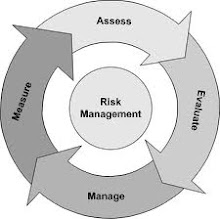.jpg)


.jpg)


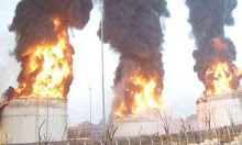


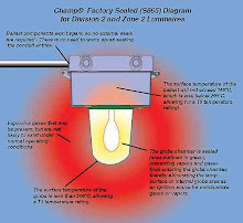


.jpg)

.jpg)


.jpg)


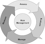


.jpg)


.jpg)


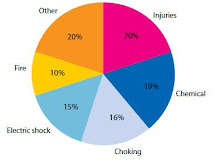


.jpg)


